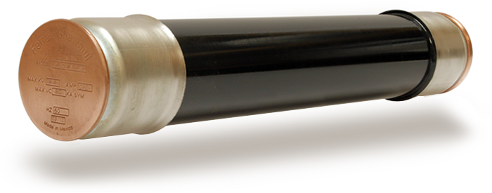
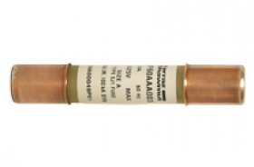
GE LIMIT AMP STARTER FUSES
Limit Amp Style Bolt-in R-rated Motor Starter Fuses are current-limiting, high interrupting rating fuses intended for the short-circuit protection of General Electric Limit amp brand of medium voltage motors and motor controllers.
MOUNTINGS
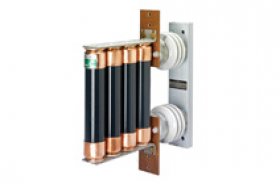
Mersen's General Electric Fuse support and disconnecting switches are used for mounting and installing medium voltage fuses. Live parts and accessories are also supported.
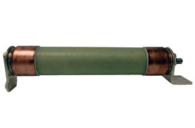
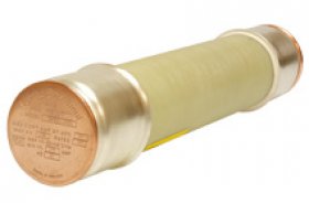
GENERAL PURPOSE CL POWER FUSES
Mersen's General Electric General Purpose fuses provide excellent over-current protection and noiseless operation. They also protect transformers and distribution lines.
POTENTIAL TRANSFORMER FUSES
Mersen's General Electric PT fuses are small dimension, ferrule type current limiting fuses with high IR that is perfect for the protection of potential transformers.
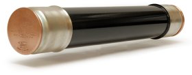
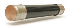
MOTOR STARTING FERRULE FUSES
Mersen's General Electric R-Rated fuses are current-limiting, high interrupting rated fuses that are intended for the short circuit protection of medium voltage motor and motor controls.
E-RATED POWER DISTRIBUTION
Mersen's General Electric E-Rated Power Distribution fuses offer dependable high-speed interruption of high-magnitude short circuit currents.
Welcome to GeneralElectricFuses.com, your top online resource for fuses from General Electric. Acquired in 2007, these products are now manufactured by Mersen, but still carry the same name consumers can trust.
With an extensive line of current-limiting fuses, fuse supports and disconnect switches, GE's line of products comes second-to-none in the protection of your expensive equipment. They also offer a high interruption capacity and noiseless operation.
As a leading distributor for General Electric fuses, we look forward to serving your needs and making sure your fuses arrive to you when you need them. In addition, with all fuses coming with a manufacturer's warranty and 24/7 customer service, you can't go wrong.